Job Deck File (.jdf) Contents
One or more Job Deck Files is required for each holder to be exposed. These files can be named as you like, but I’d recommend you name them similar to your associated schedule (and thus magazine) file, to be as clear as possible. For example, if you have schedule file: WIDGET2.sdf, which will compile to create the magazine file: WIDGET2.mgn, and your exposure is setup in 3 segments in independent Job Deck Files, then I’d recommend you name the associated Job Deck files like: WIDGET2A.jdf, WIDGET2B.jdf, and WIDGET2C.jdf.
Within a Job Deck File, there are two distinct sections:
- A Common Block
- One or More Layer Blocks
Job Deck Files are designed so that if you are using multiple e-beam layers on the same chips, you can have all relevant information in the same jobfiles, but indicated by different Layer blocks within the files. At expose time, you specify the Job Deck file as well as which layer defined in that file you wish to expose.
Common Block
JOB [/W] [‘name’] , d1 [ , d2]
Defines the beginning of a jobdeck, specifying the name, and type and size of substrate. The name is optional, and is used only for identification, and can be up to 9 uppercase letters or numbers. The shape defaults to a rectangle such as a mask or chip. Including the “/W” indicates the substrate is round, as in “Wafer”. The size indication is in units of inches by default; appending M to the units indicates Millimeters. Optionally, you can add a second diameter, smaller than the first, which indicates a cut-out circle beyond which no writing will occur.
(Required)
Examples:
JOB 5
In this simplest case, defines the substrate to be a 5” mask plate.JOB /W , 3
Defines the job for a 3” waferJOB /W ‘RICKSJOB’, 100M , 95M
A job on a 4” wafer, with nothing written on the outer 5 mm of the wafer.
PATH [‘name’]
Defines the beginning of writing path, a block of pattern exposures governed by a set of calibration routines as defined by the Path Name. The “Path Name” is chosen from a system-defined list of path sequences, as listed here. Details of how the parts of the PATH command work are described here. If you aren’t sure which PATH is best to use, or you think a different PATH definition is appropriate for your job, check with me. It is possible to define new PATH sequences as we need to. Note that each PATH segment in your JDF file must end with a PEND command.
(Required, Multiple possible, but not nested.)
Example:
PATH MASK05
Write using the PATH05 system definitions.
PEND
Marks the end of a writing path definition started with a PATH command.
(Required)
Example:
PEND
[a:]ARRAY (x, m, p) / ( y, n, q)
Declares an array of chips on the substrate. Specifically, the command defines a rectangular matrix of “array points”, which are locations from which patterns can be placed, using the ASSIGN command. Arrays can be single-level assignments, in which a single pattern is assigned at each defined array point location, or can be more complicated hierarchical definitions in which sub-arrays are assigned to some or all of the array points in a higher-level array definition.In the array definition, (x,y) is the location of the upper left array point, the array origin.
(m,n) give the array dimension counts in the x and y axes respectively, with m being the number of columns and n the number of rows.
(p,q) defines the spacing of the array points in the X and Y directions respectively.
Note that in Arrays, Y increases downward from the upper left corner array position -- the upper left corner is array index (1,1).
You can define up to 99 different arrays in a job, and an array can have up to 255 rows or columns.
(Optional)
Example 1 :
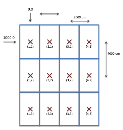
ARRAY (0, 4, 2000) / ( 1000, 3, 4000) 5
Defines an array of 12 array points, with the upper left array point located at location (0,1000 on the substrate. The array has 4 columns spaced by 2 mm and 3 rows spaced by 4 mm, as shown in this figure.
Note: It isn’t required by the syntax, but I strongly recommend that you use spaces or tabs in your jdf file to indent nested commands such as ARRAYs. Just as with computer code, it makes understanding, updating, and debugging the job files much easier.
For more information and examples of using ARRAYs, see this page, or the full jobfile examples.
AEND
Marks the end of an ARRAY definition started with an ARRAY command.
(Required)
Example:
AEND
P The “P” command can appear here in the .jdf common block, but it is far more likely to be in the Layer Block (see below), because it would be unusual to want the exact same pattern file in different layers. So see the description of the P command below in the Layer Block.
ASSIGN P(i) -> ( j , k )
or
ASSIGN A(i) -> ( ( j1-j2 ), ( k1 - k2 ), t )The ASSIGN command assigns either pattern files or sub-arrays to specific array points in the current array definition. In the case of assigning a pseudo-pattern to array points, the P(i) syntax is used; the A(j) syntax assign a subarray to the array points. Additionally, a set of doses, called a “shot modulation table” can optionally be assigned as well. For the array indices, this can be a single row or column index, a range of indices specified by a hyphen “-”, or a wildcard asterisk “*” character to indicate all values of the given index. Also, multiple patterns or sub-arrays can be assigned to the defined array points by joining the patterns or subarray indicators with a “+” sign.
(Optional, Multiple OK.)
Example:
ASSIGN P(2) -> ( * , 2-4 )
Assigns the pattern file with pseudo-pattern index # 2 to be exposed at all columns of rows 2, 3, & 4 in the array.
ASSIGN P(3) + A(2) -> ( (1-2 , * ), ‘DOSE1’ )
Assigns both the pattern file with pseudo-pattern index # 3 and the sub-array identified as #2 to be exposed at all rows of columns 1 and 2in the array, and further, to be exposed using the doses in the shot modulation table named: DOSE1. (see the MODULAT command for information on shot modulation tables.)
SKIP ( j1 - j2 , k1 - k2 )The SKIP command cancels pattern or sub-array assignments made in prior ASSIGN commands. Depending on the details of your layout, this may be an easier way to define your layout. A common example of the SKIP command is to define what is often called a “Drop-Out” - one or two dies in your wafer that you do not want to expose with the main pattern, so that, for example, you might write a test pattern in these sites instead.
(Optional, Multiple OK.)
Example:
ASSIGN P(2) -> ( * , * )
SKIP (3,4)
SKIP (6,2)
Results in pseudo-pattern # 2 being written in all sites of the defined array EXCEPT for (3,4) and (6,2), which in this example, would have no pattern exposed.
Layer Block(s)
Commands put into the Layer Block of a JDF file are typically specific to just one layer of that job. If the commands apply to more than one layer, they might be better placed into the Common Block.
LAYER n
Defines the start of the Layer Block for layer # n. You can define up to 99 layers in a job, numbered from 1 to 99.
(Optional, Multiple OK.)
Example:
LAYER 2
Defines the start of the layer-specific information for Layer 2.
P(i) ‘patfile’ [ (dx, dy) ]
The P command assigns a specific pattern file to what the JEOL documentation calls a “pseudo pattern number”. This is just an integer index number between 1 and 99 used to identify the pattern(s) in your job. This “pseudo pattern number” is then used by the ASSIGN command to specify which patterns are to be written at which array points within the layout.
Optionally, the P command can also add an offset to shift the pattern file placement. By default, the pattern file will be placed with its “chip center” located directly at the assigned array point. If positive shift numbers are given, the pattern is shifted to the right and upward. Shift values are in microns. In addition, some specialty writing modes can be selected with further options to the “P” command; those won’t be covered here yet.
(Optional, Multiple OK.)
Example:
P(2) ‘MYPAT2.v30’
Assigns the pattern file named “MYPAT2” to pseudo-pattern # 2. This pattern file will be written at whichever array points have pseudo-pattern # 2 assigned with the ASSIGN command.
P(5) ‘APATTERN.v30’ (-100,100)
Assigns pattern file “APATTERN” to pseduo-pattern # 5. This pattern will be written with its chip center shifted 100 um to the left and 100 um upward from any array points assigned with pattern #5.
RESIST {A_dose} , { L_dose } [ , {L_mode} ]
Defines the “base area dose” for this layer, and optionally, the base line dose as well. See the page describing Dose Assignments for more details about how doses are assigned to specific shapes. The Area Dose value is given in uC/cm^2. The Line Dose units depend on the value of the 3rd parameter. If the {line_dose_mode} is “A” or omitted, the line_dose value is also given in uC/cm^2; if the {line_dose_mode} value is “L”, then the {line_dose} value is interpreted as being in units of nC/cm, ie, a true line dose.
(Required)
Example:
RESIST 1000, 2.4, ‘L’
Defines the base area dose as 1000 uC/cm^2, and the base line dose as 2.4 nC/cm.
SHOT {mode} , { shot_pitch }
Defines the mode of the Dose Computation, which should pretty much always be “A”, for Automatic, as well as the “Shot Pitch” to be used. See the page describing Exposure Basics to understand the implication of the “Shot Pitch” parameter, as well as the Dose Assignments page to see how this value is used for dose computation. Valid values for Shot Pitch are 1, or even integers from 2-254.
(Required)
Example:
SHOT A , 12
Defines the dose computation mode as “Automatic”, and the Shot Pitch as 12, which indicates a shot spacing (exposure grid) of 12 nm for 4th-lens writing, and 1.5 nm for 5th-lens jobs.
t : MODULAT ( ( {shot_rank} , { mod } )
[ , ( sr2, mod2) ].... )
Defines a shot modulation table, which describes the dose to be used for shapes of Shot Rank. The doses are defined as relative, or as a percentage modulation from the Base Dose as specified with the RESIST command. See the page describing Exposure Basics to understand the implication of the “Shot Pitch” parameter, as well as the Dose Assignments page to see how this value is used for dose computation. This command creates a “Dose Modulation Table” which defines up to 255 different modulations to be used within a pattern exposure. The table is assigned to specific placements of a pattern using the ASSIGN command. The values in the modulation table are all relative to the base dose defined in the RESIST command.
(Required)
Example:
DOSE1 : MODULAT (( 1, -10) , (2, 30))
Defines a dose modulation table named “DOSE1” in which Shot Rank # 1 will receive 10% less dose than the base dose, Shot Rank # 2 will receive 30% more dose than the base dose, and all other Shot Ranks, including 0, will receive the base dose exposure.
EOS {mode},{name}
Specifies the EOS mode and condition file name to use for the exposure.
or
ASSIGN A(i) -> ( ( j1-j2 ), ( k1 - k2 ), t )The ASSIGN command assigns either pattern files or sub-arrays to specific array points in the current array definition. In the case of assigning a pseudo-pattern to array points, the P(i) syntax is used; the A(j) syntax assign a subarray to the array points. Additionally, a set of doses, called a “shot modulation table” can optionally be assigned as well. For the array indices, this can be a single row or column index, a range of indices specified by a hyphen “-”, or a wildcard asterisk “*” character to indicate all values of the given index. Also, multiple patterns or sub-arrays can be assigned to the defined array points by joining the patterns or subarray indicators with a “+” sign.
(Optional, Multiple OK.)
Example:
ASSIGN P(2) -> ( * , 2-4 )
Assigns the pattern file with pseudo-pattern index # 2 to be exposed at all columns of rows 2, 3, & 4 in the array.ASSIGN P(3) + A(2) -> ( (1-2 , * ), ‘DOSE1’ )
Assigns both the pattern file with pseudo-pattern index # 3 and the sub-array identified as #2 to be exposed at all rows of columns 1 and 2in the array, and further, to be exposed using the doses in the shot modulation table named: DOSE1. (see the MODULAT command for information on shot modulation tables.)
SKIP ( j1 - j2 , k1 - k2 )The SKIP command cancels pattern or sub-array assignments made in prior ASSIGN commands. Depending on the details of your layout, this may be an easier way to define your layout. A common example of the SKIP command is to define what is often called a “Drop-Out” - one or two dies in your wafer that you do not want to expose with the main pattern, so that, for example, you might write a test pattern in these sites instead.
(Optional, Multiple OK.)
Example:
ASSIGN P(2) -> ( * , * )
SKIP (3,4)
SKIP (6,2)
Results in pseudo-pattern # 2 being written in all sites of the defined array EXCEPT for (3,4) and (6,2), which in this example, would have no pattern exposed.
Layer Block(s)
Commands put into the Layer Block of a JDF file are typically specific to just one layer of that job. If the commands apply to more than one layer, they might be better placed into the Common Block.
LAYER n
Defines the start of the Layer Block for layer # n. You can define up to 99 layers in a job, numbered from 1 to 99.
(Optional, Multiple OK.)
Example:
LAYER 2
Defines the start of the layer-specific information for Layer 2.
P(i) ‘patfile’ [ (dx, dy) ]
The P command assigns a specific pattern file to what the JEOL documentation calls a “pseudo pattern number”. This is just an integer index number between 1 and 99 used to identify the pattern(s) in your job. This “pseudo pattern number” is then used by the ASSIGN command to specify which patterns are to be written at which array points within the layout.
Optionally, the P command can also add an offset to shift the pattern file placement. By default, the pattern file will be placed with its “chip center” located directly at the assigned array point. If positive shift numbers are given, the pattern is shifted to the right and upward. Shift values are in microns. In addition, some specialty writing modes can be selected with further options to the “P” command; those won’t be covered here yet.
(Optional, Multiple OK.)
Example:
P(2) ‘MYPAT2.v30’
Assigns the pattern file named “MYPAT2” to pseudo-pattern # 2. This pattern file will be written at whichever array points have pseudo-pattern # 2 assigned with the ASSIGN command.
P(5) ‘APATTERN.v30’ (-100,100)
Assigns pattern file “APATTERN” to pseduo-pattern # 5. This pattern will be written with its chip center shifted 100 um to the left and 100 um upward from any array points assigned with pattern #5.
RESIST {A_dose} , { L_dose } [ , {L_mode} ]
Defines the “base area dose” for this layer, and optionally, the base line dose as well. See the page describing Dose Assignments for more details about how doses are assigned to specific shapes. The Area Dose value is given in uC/cm^2. The Line Dose units depend on the value of the 3rd parameter. If the {line_dose_mode} is “A” or omitted, the line_dose value is also given in uC/cm^2; if the {line_dose_mode} value is “L”, then the {line_dose} value is interpreted as being in units of nC/cm, ie, a true line dose.
(Required)
Example:
RESIST 1000, 2.4, ‘L’
Defines the base area dose as 1000 uC/cm^2, and the base line dose as 2.4 nC/cm.
SHOT {mode} , { shot_pitch }
Defines the mode of the Dose Computation, which should pretty much always be “A”, for Automatic, as well as the “Shot Pitch” to be used. See the page describing Exposure Basics to understand the implication of the “Shot Pitch” parameter, as well as the Dose Assignments page to see how this value is used for dose computation. Valid values for Shot Pitch are 1, or even integers from 2-254.
(Required)
Example:
SHOT A , 12
Defines the dose computation mode as “Automatic”, and the Shot Pitch as 12, which indicates a shot spacing (exposure grid) of 12 nm for 4th-lens writing, and 1.5 nm for 5th-lens jobs.
t : MODULAT ( ( {shot_rank} , { mod } )
[ , ( sr2, mod2) ].... )
Defines a shot modulation table, which describes the dose to be used for shapes of Shot Rank. The doses are defined as relative, or as a percentage modulation from the Base Dose as specified with the RESIST command. See the page describing Exposure Basics to understand the implication of the “Shot Pitch” parameter, as well as the Dose Assignments page to see how this value is used for dose computation. This command creates a “Dose Modulation Table” which defines up to 255 different modulations to be used within a pattern exposure. The table is assigned to specific placements of a pattern using the ASSIGN command. The values in the modulation table are all relative to the base dose defined in the RESIST command.
(Required)
Example:
DOSE1 : MODULAT (( 1, -10) , (2, 30))
Defines a dose modulation table named “DOSE1” in which Shot Rank # 1 will receive 10% less dose than the base dose, Shot Rank # 2 will receive 30% more dose than the base dose, and all other Shot Ranks, including 0, will receive the base dose exposure.
EOS {mode},{name}
Specifies the EOS mode and condition file name to use for the exposure.
Example:
ASSIGN P(2) -> ( * , * )
SKIP (3,4)
SKIP (6,2)
Results in pseudo-pattern # 2 being written in all sites of the defined array EXCEPT for (3,4) and (6,2), which in this example, would have no pattern exposed.
Defines the start of the Layer Block for layer # n. You can define up to 99 layers in a job, numbered from 1 to 99.
(Optional, Multiple OK.)
Example:
LAYER 2
Defines the start of the layer-specific information for Layer 2.
P(i) ‘patfile’ [ (dx, dy) ]
The P command assigns a specific pattern file to what the JEOL documentation calls a “pseudo pattern number”. This is just an integer index number between 1 and 99 used to identify the pattern(s) in your job. This “pseudo pattern number” is then used by the ASSIGN command to specify which patterns are to be written at which array points within the layout.
Optionally, the P command can also add an offset to shift the pattern file placement. By default, the pattern file will be placed with its “chip center” located directly at the assigned array point. If positive shift numbers are given, the pattern is shifted to the right and upward. Shift values are in microns. In addition, some specialty writing modes can be selected with further options to the “P” command; those won’t be covered here yet.
(Optional, Multiple OK.)
Example:
P(2) ‘MYPAT2.v30’
Assigns the pattern file named “MYPAT2” to pseudo-pattern # 2. This pattern file will be written at whichever array points have pseudo-pattern # 2 assigned with the ASSIGN command.P(5) ‘APATTERN.v30’ (-100,100)
Assigns pattern file “APATTERN” to pseduo-pattern # 5. This pattern will be written with its chip center shifted 100 um to the left and 100 um upward from any array points assigned with pattern #5.
RESIST {A_dose} , { L_dose } [ , {L_mode} ]
Defines the “base area dose” for this layer, and optionally, the base line dose as well. See the page describing Dose Assignments for more details about how doses are assigned to specific shapes. The Area Dose value is given in uC/cm^2. The Line Dose units depend on the value of the 3rd parameter. If the {line_dose_mode} is “A” or omitted, the line_dose value is also given in uC/cm^2; if the {line_dose_mode} value is “L”, then the {line_dose} value is interpreted as being in units of nC/cm, ie, a true line dose.
(Required)
Example:
RESIST 1000, 2.4, ‘L’
Defines the base area dose as 1000 uC/cm^2, and the base line dose as 2.4 nC/cm.
SHOT {mode} , { shot_pitch }
Defines the mode of the Dose Computation, which should pretty much always be “A”, for Automatic, as well as the “Shot Pitch” to be used. See the page describing Exposure Basics to understand the implication of the “Shot Pitch” parameter, as well as the Dose Assignments page to see how this value is used for dose computation. Valid values for Shot Pitch are 1, or even integers from 2-254.
(Required)
Example:
SHOT A , 12
Defines the dose computation mode as “Automatic”, and the Shot Pitch as 12, which indicates a shot spacing (exposure grid) of 12 nm for 4th-lens writing, and 1.5 nm for 5th-lens jobs.
t : MODULAT ( ( {shot_rank} , { mod } )
[ , ( sr2, mod2) ].... )
Defines a shot modulation table, which describes the dose to be used for shapes of Shot Rank. The doses are defined as relative, or as a percentage modulation from the Base Dose as specified with the RESIST command. See the page describing Exposure Basics to understand the implication of the “Shot Pitch” parameter, as well as the Dose Assignments page to see how this value is used for dose computation. This command creates a “Dose Modulation Table” which defines up to 255 different modulations to be used within a pattern exposure. The table is assigned to specific placements of a pattern using the ASSIGN command. The values in the modulation table are all relative to the base dose defined in the RESIST command.
(Required)
Example:
DOSE1 : MODULAT (( 1, -10) , (2, 30))
Defines a dose modulation table named “DOSE1” in which Shot Rank # 1 will receive 10% less dose than the base dose, Shot Rank # 2 will receive 30% more dose than the base dose, and all other Shot Ranks, including 0, will receive the base dose exposure.
EOS {mode},{name}
Specifies the EOS mode and condition file name to use for the exposure.
Example:
SHOT A , 12
Defines the dose computation mode as “Automatic”, and the Shot Pitch as 12, which indicates a shot spacing (exposure grid) of 12 nm for 4th-lens writing, and 1.5 nm for 5th-lens jobs.
[ , ( sr2, mod2) ].... )
Defines a shot modulation table, which describes the dose to be used for shapes of Shot Rank. The doses are defined as relative, or as a percentage modulation from the Base Dose as specified with the RESIST command. See the page describing Exposure Basics to understand the implication of the “Shot Pitch” parameter, as well as the Dose Assignments page to see how this value is used for dose computation. This command creates a “Dose Modulation Table” which defines up to 255 different modulations to be used within a pattern exposure. The table is assigned to specific placements of a pattern using the ASSIGN command. The values in the modulation table are all relative to the base dose defined in the RESIST command.
(Required)
Example:
DOSE1 : MODULAT (( 1, -10) , (2, 30))
Defines a dose modulation table named “DOSE1” in which Shot Rank # 1 will receive 10% less dose than the base dose, Shot Rank # 2 will receive 30% more dose than the base dose, and all other Shot Ranks, including 0, will receive the base dose exposure.
EOS {mode},{name}
Specifies the EOS mode and condition file name to use for the exposure.
(Required, Multiple OK)
At UW, Mode will always be either 3 (4th lens, 100kV), or 6 (5th lens, 100 kV). Condition files are created by the machine staff, and you can see the present status of available condition files here. The SCHD compiler will require that the condition file you specify exists on the machine.
Note that you can also set the EOS in the cassette block of the schedule file. A specification in the schedule file will supercede any definition here in the job deck file layer block.
Example:
EOS 3,‘2nA_AP5_M3’
Will set the column to use EOS Mode # 3 (aka 4th lens, 100 kV), with the Condition File called: “2nA_AP5_M3”.
OBJAPT {aperture_number}
This command is only a comment -- the actual aperture to be used is defined in the Condition File, which is chosen using the EOS statement. This command is used only as a comment to indicate which conditions you are using. For the actual aperture sizes in use, see the Aperture Table.
(Optional)
Example:
OBJAPT 5
Indicates Aperture # 5, a 60 um aperture is intended to be used with this job file.
STDCUR {beam_current}
This command tells the compiler what beam current you intend to use. This command does NOT change the beam current of the system -- you must use the EOSSET sub-program of the CALIB program to do that. The value you use here is, however, used to compute the predicted clock rate(s) for your job, based on the Base Dose and MODULAT commands in your job, and will warn you if the conditions you specify will push your job outside the hardware limitations. For the possible beam currents defined, see the List of Available Condition Files. The value specified is always in nA.
(Optional)
Example:
STDCUR 2.0
Indicates a 2 nA beam current is intended to be used with this job file.
RESTYP {type_of_resist} , { name_of_resist}
This command is only a comment -- the resist you put on the wafer is, of course, entirely up to you. This command is used only as a comment to indicate which conditions you are using. For some suggested resist processes, see the Process section of this website. type {type_of_resist} parameter must be exactly either "POSI" or "NEGA", adn the {name_of_resist} can be a string of up to 20 alphanumeric characters.
(Optional)
Example:
RESTYP POSI , ‘PMMA’
Indicates a postive-tone resist, PMMA, is intended to be used with this job file.
Footer Block
Yes, you have to end your file with a footer.
END
Marks the end of the jobdeck. Each .jdf file must end with an END command.
(Required)
Example:
END
Example:
RESTYP POSI , ‘PMMA’
Indicates a postive-tone resist, PMMA, is intended to be used with this job file.
Example:
END