Doses
There are several commands used together that will define at which exposure dose(s) your pattern will be exposed.
Dose Setting Commands
Within your set of job files, you must define the Base Dose using the RESIST Command, and the Dose Computation mode using the SHOT command. If this is all you do, all shapes on all shot ranks in all pattern placements will be written using just this base dose.
You can modify the actual exposure dose of any Shot Rank, for any pattern placements, by defining a modified set of doses using the MODULAT command, and then indicating which placements of each pattern are to get which dose assignments using the ASSIGN command.
Note that some commands, including the MODULAT and RESIST commands, can appear in both a JDF file and the SDF file. If specified in both files, any RESIST or MODULAT defined in the SDF file will override the same shot rank modulation defined in the JDF layer block. My advice is to avoid the confusing and ambiguous situation and use dose setting commands in either the SDF or the JDF, but not both.
MODULAT and Dose
One key but possibly confusing point to understand is that you don’t specify the actual exposure dose you want. Instead, you specify two quantities which are used together to compute the actual dose for each specified Shot Rank assignment. 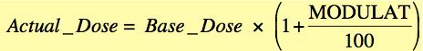
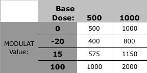
This table shows the actual exposure dose for various values of Base Dose and MODULAT.
RESIST {A_dose} , { L_dose } [ , {L_mode} ]
Defines the “base area dose” for this layer, and optionally, the base line dose as well. The Area Dose value is given in uC/cm^2. The Line Dose units depend on the value of the 3rd parameter. If the {line_dose_mode} is “A” or omitted, the line_dose value is also given in uC/cm^2; if the {line_dose_mode} value is “L”, then the {line_dose} value is interpreted as being in units of nC/cm, ie, a true line dose.
(Required)
Example:
RESIST 1000, 2.4, ‘L’
Defines the base area dose as 1000 uC/cm^2, and the base line dose as 2.4 nC/cm.
SHOT {mode} , { shot_pitch }
Defines the mode of the Dose Computation, which should pretty much always be “A”, for Automatic, as well as the “Shot Pitch” to be used. See the page describing Exposure Basics to understand the implication of the “Shot Pitch” parameter, as well as the Dose Assignments page to see how this value is used for dose computation.(Required)
Example:
SHOT A , 12
Defines the dose computation mode as “Automatic”, and the Shot Pitch as 12, which indicates a shot spacing (exposure grid) of 12 nm for 4th-lens writing, and 1.5 nm for 5th-lens jobs.
t : MODULAT ( ( {shot_rank} , { mod } )
[ , ( sr2, mod2) ].... )
Defines the mode of the Dose Computation, which should pretty much always be “A”, for Automatic, as well as the “Shot Pitch” to be used. See the page describing Exposure Basics to understand the implication of the “Shot Pitch” parameter, as well as the Dose Assignments page to see how this value is used for dose computation. This command creates a “Dose Modulation Table” which defines up to 255 different modulations to be used within a pattern exposure. The table is assigned to specific placements of a pattern using the ASSIGN command. The values in the modulation table are all relative to the base dose defined in the RESIST command.
(Required)
Example:
DOSE1 : MODULAT (( 1, -10) , (2, 30))
Defines a dose modulation table named “DOSE1” in which Shot Rank # 1 will receive 10% less dose than the base dose, Shot Rank # 2 will receive 30% more dose than the base dose, and all other Shot Ranks, including 0, will receive the base dose exposure.
ASSIGN P(i) -> ( j , k )
or
ASSIGN A(i) -> ( ( j1-j2 ), ( k1 - k2 ), t )The ASSIGN command assigns either pattern files or sub-arrays to specific array points in the current array definition. In the case of assigning a pseudo-pattern to array points, the P(i) syntax is used; the A(j) syntax assign a subarray to the array points. Additionally, a set of doses, called a “shot modulation table” can optionally be assigned as well. For the array indices, this can be a single row or column index, a range of indices specified by a hyphen “-”, or a wildcard asterisk “*” character to indicate all values of the given index. Also, multiple patterns or sub-arrays can be assigned to the defined array points by joining the patterns or subarray indicators with a “+” sign.
(Optional, Multiple OK.)
Example:
ASSIGN P(2) -> ( * , 2-4 )
Assigns the pattern file with pseudo-pattern index # 2 to be exposed at all columns of rows 2, 3, & 4 in the array.
ASSIGN P(3) + A(2) -> ( (1-2 , * ), ‘DOSE1’ )
Assigns both the pattern file with pseudo-pattern index # 3 and the sub-array identified as #2 to be exposed at all rows of columns 1 and 2in the array, and further, to be exposed using the doses in the shot modulation table named: DOSE1. (see the MODULAT command for information on shot modulation tables.)
Examples
In the JDF Common Block:
21: ARRAY ( -1000,1,1000 )/( 1000,10,242 )
ASSIGN P(2) -> ((*,*), DOS1)
22: ARRAY ( -1000,1,1000 )/( 1000,10,242 )
ASSIGN P(2) -> ((*,*), DOS2)
23: ARRAY ( -1000,1,1000 )/( 1000,10,242 )
ASSIGN P(2) -> ((*,*), DOS3)
24: ARRAY ( -1000,1,1000 )/( 1000,10,242 )
ASSIGN P(2) -> ((*,*), DOS4)
In the JDF Layer Block:
SHOT A,4
RESIST 1015,1000
DOS1: MODULAT ((0,-25))
DOS2: MODULAT ((0,-12.5))
DOS3: MODULAT ((0,0))
DOS4: MODULAT ((0,20))
In this setup, there will be 4 small arrays of Pattern P(2) placed on the wafer, each at a different dose. Based on the combination of RESIST and MODULAT commands, the actual written doses in this case will be:
761 uC/cm2 888.1 uC/cm2 1015 uC/cm2 1218 uC/cm2
Example #2, Multiple Doses within a Pattern File
If you’ve defined multiple doses within a pattern file, either manually or automatically, you need to define the various dose for each assigned “Shot Rank”, or else all shapes assigned to any undefined Shot Rank will be written at the Base Dose, which may or may not be what you want!
For example, if you’ve designed your pattern like this example, and processed it like this example, then in your JDF file, you would need something like:
MODULAT ((1,50),(2,20),(3,-10))
This will cause the narrow line to be written at 50% higher dose than base dose, the intermediate connections to be written at 20% higher dose than base dose, and the large pads to be written at 10% less than base dose. Of course, you can always assign multiple shot ranks the same exposure dose, so if in this example you wanted to assign the intermediate and large pads the same dose, you’d just assign both Shot Ranks 2 and 3 to the same Modulation value.
Useful Tools
I’ve created a few online tools to do MODULAT and DOSE calculations for you:
MODULAT From Dose
Dose From MODULAT
Example:
ASSIGN P(2) -> ( * , 2-4 )
Assigns the pattern file with pseudo-pattern index # 2 to be exposed at all columns of rows 2, 3, & 4 in the array.
ASSIGN P(3) + A(2) -> ( (1-2 , * ), ‘DOSE1’ )
Assigns both the pattern file with pseudo-pattern index # 3 and the sub-array identified as #2 to be exposed at all rows of columns 1 and 2in the array, and further, to be exposed using the doses in the shot modulation table named: DOSE1. (see the MODULAT command for information on shot modulation tables.)
21: ARRAY ( -1000,1,1000 )/( 1000,10,242 )
ASSIGN P(2) -> ((*,*), DOS1)
22: ARRAY ( -1000,1,1000 )/( 1000,10,242 )
ASSIGN P(2) -> ((*,*), DOS2)
23: ARRAY ( -1000,1,1000 )/( 1000,10,242 )
ASSIGN P(2) -> ((*,*), DOS3)
24: ARRAY ( -1000,1,1000 )/( 1000,10,242 )
ASSIGN P(2) -> ((*,*), DOS4)
SHOT A,4
RESIST 1015,1000
DOS1: MODULAT ((0,-25))
DOS2: MODULAT ((0,-12.5))
DOS3: MODULAT ((0,0))
DOS4: MODULAT ((0,20))
761 uC/cm2 888.1 uC/cm2 1015 uC/cm2 1218 uC/cm2
MODULAT From Dose
Dose From MODULAT