Manual Dose Assignment with Dose Mapping
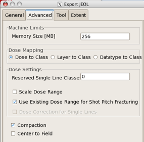
(In earlier versions of LayoutBEAMER, this feature did not work properly for our JEOL system. As of LayoutBEAMER 4.1.4, March 2011, this feature is now working.)This feature allows you to simply map Layer OR Datatype of the shapes in your input pattern to Shot Rank number in the JEOL J52 file, with one simple step. You find this option in the Export Module, under the Advanced tab
If you have any data in your .gds file that you do not want to expose, use an EXTRACT module to select just the Layers and/or Datatypes that you want to appear in your output file.
Do not use HEAL or Overlap Removal if you want to use this option, as these options will typically remove all Layer and/or Datatype identification and merge all data on to a single Layer and Datatype. (But see below - it is possible to split your data into separate units by Layer and/or Datatype, and individually heal those units, then re-merge the data. This requires some extra modules and some careful attention to the details, and becomes increasingly tedious as the number of unique layers and/or datatypes increases, but it does work.
If your input file has shapes on Layers 1 through 10 as well as layer 14, and you select “Layer to Class” as the Dose Mapping option, your output J52 (.v30) file will have shapes on Shot Ranks 1-10 and 14. Very simple.
Manual Dose Assignment with FDA
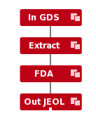
It’s easy to assign doses to different Layers or Datatypes in LayoutBEAMER. Here’s an example flow:
For the Extract module, you typically only want the layers you want to write in this e-beam write, so exclude all other layers in your design:

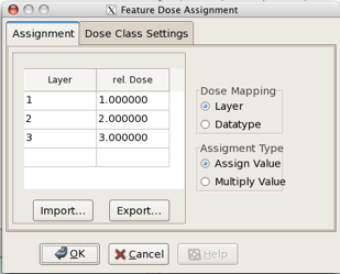
And for the FDA module, define each layer for each different dose (Shot Rank) you want (or datatype, you have to choose one or the other with the “Dose Mapping” buttons on the right), and then assign a UNIQUE “Rel Dose” for each, as shown here:
The output from this flow will then be a JEOL file with 3 different Shot Ranks:
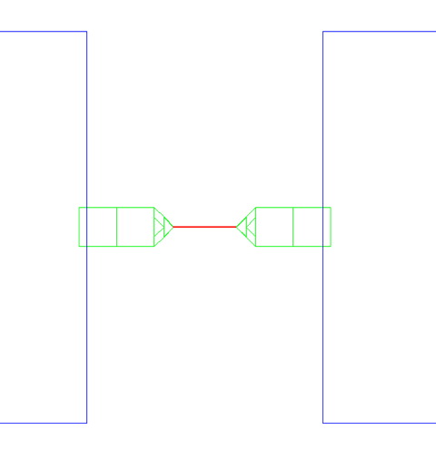
Define doses for these 3 shot ranks in your JDF file, and each segment of this pattern will be exposed at the dose you define.
Let me explain a slight oddity here about why you put in unique “Rel Dose”s into the FDA box. LayoutBEAMER wants to go one step further than just assigning the Shot Ranks into the pattern file -- it wants to help you by also creating the MODULAT command to put in your job file. When you run the flow above, it also creates a file with the same name as your pattern, but the filetype: .JDI. Here’s the contents of the file in this case: each defined Shot Rank is assigned the Relative Dose value you put in the box. You could cut-and-paste this text right in to your JDF file.
MOD001: MODULAT (( 0, 0.0 ) , ( 1, 100.0 ) , ( 2, 200.0 ))
More often than not, however, when you are creating the pattern file, you won’t really know the exact doses you want to expose at -- these are typically determined experimentally. So you have to fill in some dummy relative doses here, and then set them in your JDF file, perhaps trying a range of values, to determine the final values you’ll need to use.
But be aware that LayoutBEAMER goes even one step further in trying to be helpful. If you don’t define UNIQUE “Rel Dose” values for each layer/datatype that you want to get a different dose, LayoutBEAMER will helpfully combine all shapes of the same “Rel Dose” into the same Shot Rank, thus losing the differentiation you defined. So remember: When using FDA to define different doses, be sure to always put in unique “Rel Dose” values.
HEALING really isn’t directly compatible with Dose Assignments.
Do not use HEAL in the above flows!
In this case, you probably do NOT want to use LayoutBEAMER’s HEAL function. You will find that it will typically merge all of your shapes which you carefully differentiated into different layers. If, due to some layout issues, you find that you MUST heal the data prior to fracturing, it can still be done, but you’d have to individually extract each layer, individually Heal each layer, and then merge the results back together. Depending on how many layers you have, this may or may not be a difficult task. Here’s what the flow would look like for the 3-layer process above:
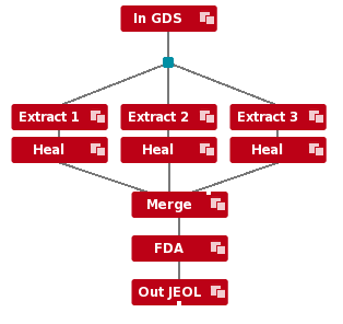
Not so bad, really, but a good demonstration that you have to understand how the various modules interact with each other, and how flexibility and capability usually come at the price of complexity.