GenISys BEAMER
(formerly: LayoutBEAMER)Note: All of these documents are proprietary and confidential to GenISys Gmbh. You agree to use them for your own research only, and you may not duplicate or transmit these documents to any other user not authorized to access these documents. In particular, you may not transmit copies of these documents to anyone outside of UW. Please help us maintain good relations with our vendors, and help our vendors maintain healthy business positions. Thanks.
GenISys Online Manual (username/password required)
GenISys Training Videos (username/password required)
Getting Started with BEAMER
Once you are properly logged-in to the EBEAM computer, from a computer providing X-Windows capability, start BEAMER by simply typing:
beamer at the command prompt. You can abbreviate this by just typing the shortcut: lb (where this is a lower-case letter “L” and “B”). BEAMER uses a flow-chart model, as shown here:
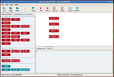
The left part of the screen is a palette of possible data modules to work with, while the top of the right part is the data flow we have defined. You build up a flow by simply dragging and dropping the various modules you need in your processing flow. But, there is some complexity hidden in here... each module has one or more configuration screens beneath it, and you’ll have to ensure that you have all of the details correct in each of these additional configuration dialogs.
Let’s look in some detail at the example shown here, which is a fairly typical minimal set of operations for a very simple e-beam data conversion. There are 4 modules in this conversion; we’ll step through each one:
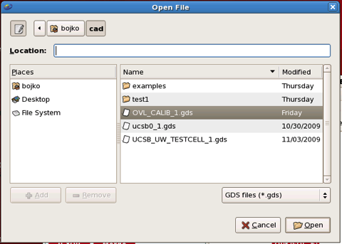
1) Read in the GDS design data.
Nothing too mysterious here; you select the type of data you wish to read in, and choose the file containing your data. There is a discussion of data formats here, and if you plan to use anything other than standard GDS-II, I’d strongly recommend you talk with me before proceeding so we can do a test of your data, to make sure we can make it work.
When you choose your input data file, you’ll get another specification screen, like this:
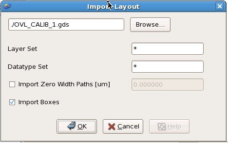
Most typically, the default options work fine. For most operations, I prefer to read in the entire file, and later select which layers I want to work with; this makes the flow a bit more universal, but it is certainly possible to read in only the defined layers that you want, with a “Layer Set” specification in the Import module.
2) Extract out the relevant parts of your data that you want to write with this ebeam file.
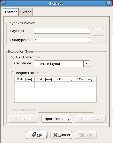
Inside the Extract module, you can choose various ways to limit down your data. Most typically, you’ll choose out just one, or some small subset, of data layers to write with your e-beam file. In this example, only layer 1 is specified. It is also possible to select data by cell (aka structure), or by geometrical region, ie. a window of layout coordinates.
3) Heal your data.
Wait, am I telling you that in order to “fracture” your data, you first have to “heal” it? Yes, in fact I am. Sorry for the apparent illogical terminology, but believe it or not, these are industry-wide terms. It doesn’t make sense, but it’s the way it is. So, what about this healing, anyway? Why heal data? There are several important reasons, but the most common example is to avoid double-exposures during your ebeam writing.
Have a look at this design snippet:
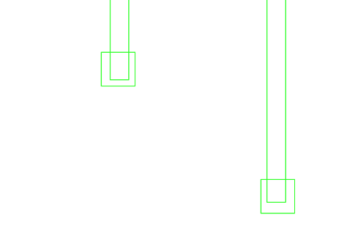
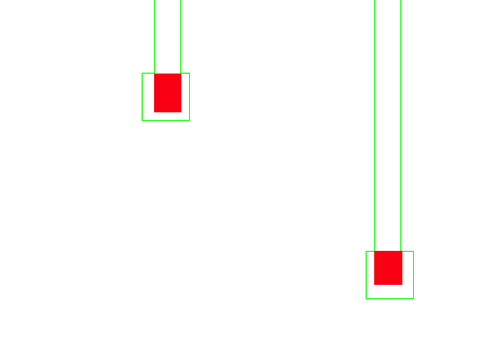
It’s a bit hard to tell from the outline view, but it turns out that the two zones highlighted in red here in the next figure would be exposed twice during the e-beam write, if you did not heal the data during the data processing. Now, double exposure may or may not hurt your pattern; it might happen in an insignificant location, so maybe you wouldn’t care. But it’s an uncontrolled variable, so best practice is to always “heal” your data prior to e-beam exposure. (There are some notable exceptions to this - there are a few specialized cases where you might intentionally want double exposures, and in the case of manual dose assignments using datatypes or layers, you have to either not heal your data, or heal it in a special way to avoid losing your manual dose assignments. But these are pretty advanced cases, and this is an introduction.)
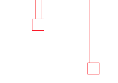
This figure shows the output of the “healing” operation, in which LayoutBEAMER looks through your data and automatically removes any overlapping regions, so that all areas of your pattern data are only written one and exactly one time, which is most typically what you want. (Yes, there are in fact a few special cases in which you might want double-exposure; in that case, of course, you wouldn’t want healing...)
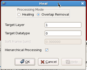
The specification for the Heal operation is quite simple: typically you would choose only the option “Overlap Removal” (although for certain types of layouts, for example curves and complex polygons, you may want to "heal" so that Beamer can do a better job of fracturing the data into e-beam format.)
4) Finally, export your data in JEOL format.
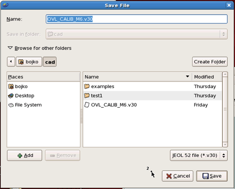
The first dialog is quite simple; you specify the name and directory for your output file. But, there is one absolutely critical option! You must select the correct data format. In this case, you will want “JEOL 52 file (*.v30) option. If you have the site defaults installed for your account, this should be the default. If it is not, see the section at the bottom of this page about installing the site defaults for your account.
After choosing the filename, you’ll be faced with a somewhat more complicated dialog:
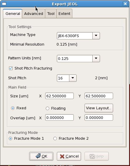
Here, in the General tab, you must make sure you choose the correct “Machine Type” JBX-6300FS. (If you have the site defaults installed for your account, this should be the default. If it is not, see the section at the bottom of this page about installing the site defaults for your account.) Then you must switch to the “Tool” tab, which looks like this:
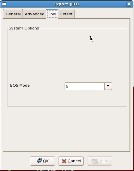
And make sure you choose the correct EOS mode you intend to expose in.
(EOS mode is described here.)
Next, go BACK to the General tab, and make sure the correct pattern units are selected for your EOS mode, either 1 nm for 4th lens or 0.125 nm for 5th lens.
In most cases, you probably don't want to use Shot Pitch Fracturing. That's a special feature useful only for certain specific cases.
The settings shown here are typical, but there are many cases where you will want to use other options as well.
Review your data processing
Because e-beam write time is expensive, and there are many options in data processing that can lead to unexpected results, you should take some time to review your data before you begin to write. You should do two forms of data review.
Graphical Review
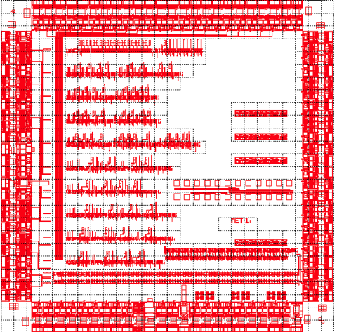
LayoutBEAMER has an excellent graphics viewer that allows you to inspect your data at each step in your data conversion process.
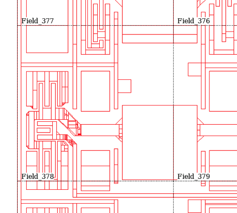
In a wide view, you can see your entire file, with the e-beam fields shown.
Zooming in, you can see the individual e-beam shapes in your pattern, and how LayoutBEAMER has rendered your data.
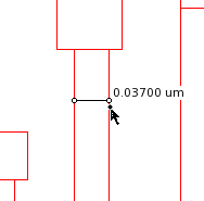
You can, and should, verify a few of your critical dimensions, to make sure they came through the conversion process accurately, and sized as you wish.
Log Text Review
There is also quite a good deal of textual information about your pattern conversion process.
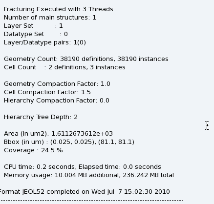
This was a pretty simple example, but you should certainly note the “Area” of your pattern. This number, when combined with machine parameters such as beam current and resist parameters such as exposure dose, will let you estimate the exposure time of your pattern.