Example 1 using LayoutEditor: Gratings, 1-D & 2-D
OK, let’s step through the process of creating a simple design in LayoutEditor. If you haven’t downloaded LayoutEditor yet, go here for details on downloading and installing it on your computer.
LayoutEditor is highly configurable, so you can modify most features of the User Interface, including which palettes and toolbars appear and where they are located on your screen, what colors various features are, etc. So your environment will likely look different from mine. My screenshots are from my Mac, but it behaves pretty much the same way on Windows and Linux.
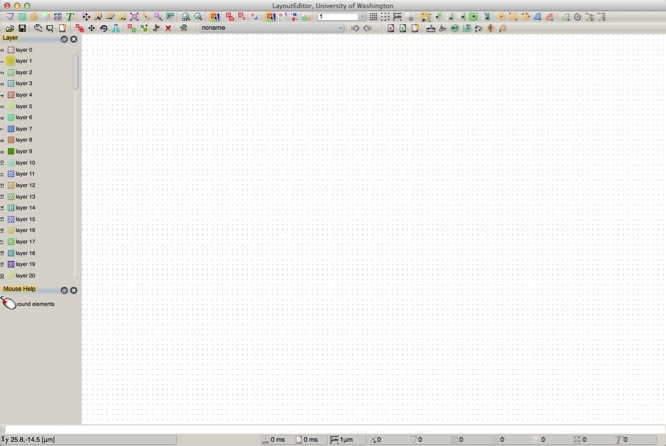
When you start LayoutEditor, you'll be in the editor with a blank library and a blank cell open and ready for you to add objects. Your screen might look like this, but again, the layout and visibility of the palettes and toolbars will likely be different.
First, you need to create a “Layout”. A “layout” contains all of the objects and layers in your design, and in general, you’ll use one layout for each distinct project. (You can think of a “layout” as a document in Microsoft Word -- inside that document, you’ll have many objects, words, paragraphs, titles, etc, but everything is in a single container, in this case, a “layout”.)
I'm presently editing a cell named "noname". If I wish to add an object to this cell, here are the steps:
1) First, select the layer for my object, by clicking on a layer in the "Layer" palette on the left.
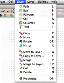
2) Next, choose what type of object to add, from the primitives discussed on the last page. On my toolbars, this is in the upper left corner, and you see, from left-to-right, Path, Box, Polygon, CellRef, CellRefArray, and Text. You can also choose the primitive type from the "Draw" menu, as shown here, or using short-cut keys.
So choose an object type. Then, start clicking in the drawing area. Each point you click adds a coordinate to your element. Watch the "Mouse Help" window, located by default in the lower left, and you'll always see what types of clicks you can make and what actions those clicks will have. These vary with the type of object and action you are doing, but might include adding additional points, undoing your previous point, closing the object you are working on, etc. Try adding some of the different object types in your drawing now.
You can also change your view of your edit by zooming and panning, under the "Zoom" menu, or by toolbar, keyboard shortcut, or mouse. Try zooming around your drawing.
You can see the object properties for any object in your database by double-clicking on that object. But this only works when you are not in the middle of adding or editing a shape - that is, the Mouse Help should show that a single left-click will "Select Element" -- if you are in the middle of editing a shape, you either need to end your edit, or press "Escape" to end the editing and get back to the base mode.
As you create new cells in your drawing, you will find that you can only edit one cell at a time - the name of the cell you are currently editing is displayed in the cell edit dropdown menu of the toolbar (noname in the screenshot above.)
You will likely notice the grid(s) displayed in your drawing window, and see that those grids change size as you zoom in and out. The drawing grid size is displayed at the bottom center of the window. Note that this grid is not the database grid, this is the display grid, and changes with your view or on your command. The database grid is set in the preferences, and is typically something very small, such as 1 nm.
You will also see lots of editing options under the various menus and toolbars, but I'll let you learn about those on your own.
For now, let's move on with the example of creating some 1-D and 2-D gratings.
Let’s start simple and make a 1-Dimensional Grating, which will look like a bunch of parallel lines.
I’m using two layers, I’m calling them “Layer 1” and “Layer 2". I've made them display in Blue and Red, respectively. You can rename, change colors and fill patterns, and otherwise configure layers in the Layer Menu, or the Layer Manager dialog.
Let's start by creating a new, empty cell to work in. Choose menu Cell : New Cell. You'll be put into a new, empty cell which will be named "noname_#". Since "noname" is pretty nondescript, let's give it a name, by choosing menu item: Cell : Cellname... In the popup, rename your cell to: one_line_2um
Select (click on it) Layer 1 in the layer palette on the left, select “Box” from the toolbar, and click at (0,0) and then (2, 100). Don't worry if those coordinates aren't correct - in many cases, such as this one, it's easier to get the box created, then set the corners to what you want. So in this case, just create a box by clicking two coordinates.
Now, if you look at the Mouse Help, you'll find that LayoutEditor assumes your going to want to keep adding boxes, so it's actually waiting for you to input the first coordinate of your next box. Well, not so fast, we want to edit the first box to make it the correct size, shape, and location. So either right-click ("End Mode") or press the "Esc" key to terminate box entry, and now let's view the properties of our box by either double-clicking on the box, or right-clicking and choosing "Properties..." from the contextual menu. The Box properties should look much like the box on the previous page. For this demo, set the left and bottom coordinates to 0, the right coordinate to 2, and the top to 100. Now your box has changed size, shape, and location to these coordinates. It's possibly even off your screen view now, so to see your box again, Zoom : Zoom Fit All, (or default shortcut key "/"). The screen should redraw to show just your new box, 2 um wide and 100 um tall. While admiring your box, you can pan and zoom using the mouse, or keyboard shortcuts, or the Zoom menu. Pan left, right, up or down with the arrow keys, or right-click-drag to pan with the mouse. Zoom in/out with the mouse wheel.
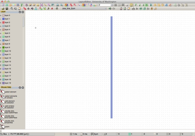
So, after editing the properties, my cell: one_line_2um looks like this:
There are keyboard and mouse shortcuts for many of these options. You can pan your view using the arrow keys, and you can zoom using the mouse wheel. You can also pan by holding shift, then right-click drag in the window to slide the window with the mouse, a bit like in Google Maps. Once you create some objects, take some time to get used to changing your view.
Alternatively, here’s another way you might find easier to get a box of an exact dimension: start by just drawing a box of arbitrary dimensions by clicking any two (different) points. Then choose “Select” in the toolbar (you can use the keyboard shortcut “Esc” to jump back to “Select” at any time). Now double-click the box you just created, and you should see the “Object Properties” box open up. Here, you can set the coordinates of the box exactly to be (0,0), (1,100). Note: In LayoutEditor dialogs, you often must click “Apply” before you close the dialog. I think this is a Unix-y behavior, but it lets you keep the dialog box open while you keep editing. You’ll get used to this if you aren’t already a Unix user.
So cell one_line_2um might now look like this:

Now make another new cell, called “1D_GRATING”. Cell : New Cell then Cell : Cellname... then name it "1D_Grating".
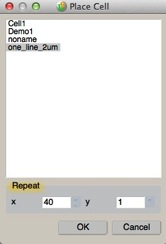
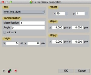
Now, in this new, empty “1D_GRATING” cell, let’s create an array of those lines by choosing “CellArray” from the Toolbar. A popup will ask you to select which cell you wish to make an array of, so choose the one_line_2um cell we just created above, and then tell it we want to make 40 repeats in X and 1 repeat in Y, as shown:
Now, in the drawing window, the mouse help tells us to click on the CellRefArray:Origin, so click on a coordinate that will be the origin of your array (as before you can change this coordinate later). The mouse help then tell you to click on the CellRefArray:Spacing. You now need to click on another coordinate, where the spacing from your origin coordinate will define the X and Y spacings of the elements in your array. Since we're defining a 1-D array, just move the mouse to the right a little bit, and click. An array of your one_line_2um elements is now added. When clicking both the origin and spacing points, you can zoom in or out, or pan, to get to the exact coordinate you wish to click on. Or, now that your array is added, you can now edit the properties of that array to get the origin and spacing exactly how you want it. As before, though, after adding a CellArray, LayoutEditor assumes you want to keep adding CellArrays, so terminate the add by either center-clicking, or pressing "Esc", but get back to the Mouse Hint "Select Element", then double-click on the array you just created. Change the values in the Properties pop-up to match those in this figure:
Click OK, then reset your view with Zoom : Zoom Fit All (or "/").
In the “Object Editor Options” pop-up, click the “...” button to the right of the Cell window and choose the “one_line_2um” cell you created just above. Leave “Scale factor” at 1, Angle at 0, and Mirror Unchecked (for now, feel free to try these out later, though -- they can be very useful!). Click the “Array Instance” box ON. Enter Rows = 1, Columns = 40, Row vector (0,0) and Column Vector (2, 0). Now click the “Apply” button. Notice that now as you move the mouse over the drawing area, you’ll see the outline of a your grating - 40 parallel lines (you may need to zoom out (mouse wheel) to see the outline.) Click on a location in your layout to place your array in your “1D_GRATING” cell. Note that this, like the other shape commands, are iterative, so if you keep clicking, you’ll keep adding more copies of the array! If you want to stop adding arrays, click on “Select” in the toolbar (or press the “Esc” key.)
And your 1-D grating might look like this:
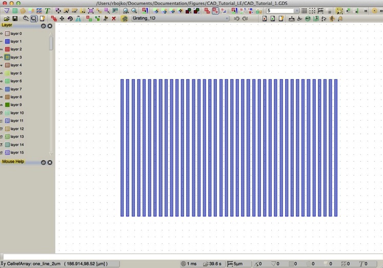
Not too bad -- 40 lines with just a few mouse clicks. But remember, from the discussion on the previous page, this isn’t exactly 40 lines -- it’s really one line, repeated in one array 40 times. So it’s really just two objects: a box (in one cell), and an array (in another cell).
Once in “Select” mode, you can select the array you just created by clicking on that array (or any other object in your drawing). As with many programs, “selected” objects show as a black outline. You can select multiple objects with control-select, and you can select all of the objects in a given area but dragging a window with the left mouse button held down. Once you have one or more objects selected, you can delete, or move, or change properties. For a single object, you can also just double-click on an object to open the “Object Properties” window.
Take some time to practice moving around a bit, zooming in and out, panning, etc. Create some new objects, add more instances of your array, maybe try out scaling or rotation. Edit some of the arrays you’ve placed. This is your drawing, do what you like!
When you’re ready to move on, create another new cell, let’s call it “one_dot”. Select “Layer 2” and create a square box (or polygon, as you wish) from (0,0) to (1,1). That is, make a square that is 1 micron on each side. That might look like this:

Next, create another new cell, “2D_GRATING”. In this cell, place an Instance of “one_dot” that is 30 x 20 placements of the “one_dot” cell, and spaced say 3 um by 4 um.
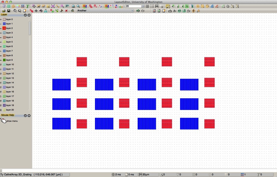
And here’s what a 2-D grating might look like:
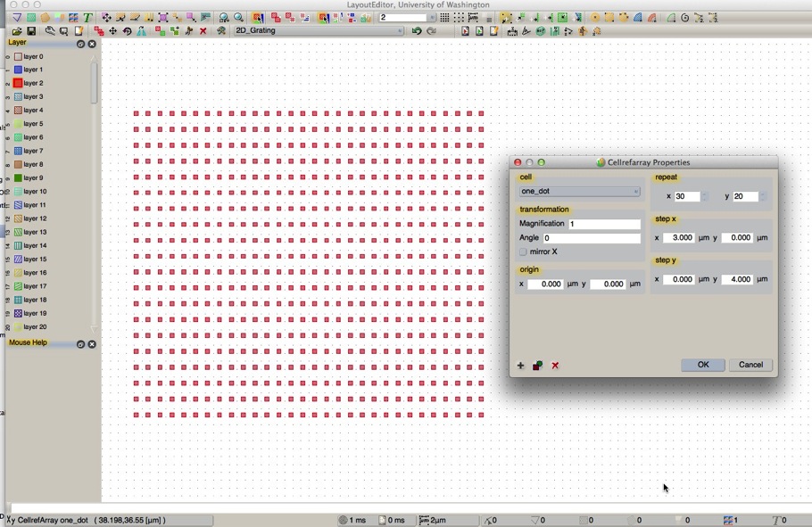
Now you have a 2-dimensional array of 600 squares. Remember, this is really just two elements, one polygon, and one array. You could change this an array that's 200 x 300 elements just as easily. 60,000 squares, still two elements.
But let’s say you determine that squares just aren’t cool anymore, and you’d rather have an array of circles. Do you have to change all 600 (or 60,000) squares? No, of course not, because you created your array using hierarchy.
Go back to editing your unit cell, by selecting “one_dot” in the “Cells” menu in the toolbar, or menu item: Cell : Select Cell...
Open the properties dialog for the square (double-click, or right-click:Properties), and notice at the lower left corner, one of the advanced features is "Convert to circle."
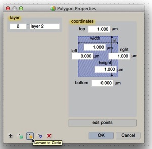
Go ahead, click it, and you'll see a new dialog:
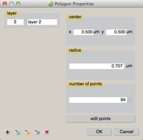
OK, now we see options for center and radius -- these are how we parameterize a circle, right? But wait, didn't I say earlier there are only a few primitives, with no mention of circles? Well, yes, If you look a bit closer, you'll notice the dialog is still labeled "Polygon Properties", and there's this entry for "Number of Points". You see, GDS-II has no circles, or no curved elements at all. This just isn't something envisioned by the originators of this data format and this type of CAD. But of course, now people frequently do curves and circles. So LayoutEditor fairly seamlessly handles the conversion for you. Circles and curves are really polygons, but if the polygons happen to form a circular shape, then LayoutEditor considers it a circle, and let's you parameterize the shape by the familiar center and radius, and handles the trigonometry necessary to place all the polygon vertices that represent that circle.
So, back in our design, you've now changed the shape in cell "one_dot" to be a circle. So what do you see if you go back to viewing the cell: "2D_Grating"?

Are you getting the hang of using LayoutEditor to make a design?
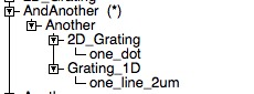
Try making another New Cell and placing some instances of your 1D_GRATING and 2D_GRATING cells in this higher-level cell. Yes, you can create cells containing cells containing cells containing cells and so forth, up to 32 levels deep (some programs may allow more; some fewer). Placing cells inside of other cells, which then may in turn be inside other cells is generally known as a cell Hierarchy, and it's a very powerful "building block" principle of this sort of CAD.
If I then create an array of this cell, that might look like this.... And so on.
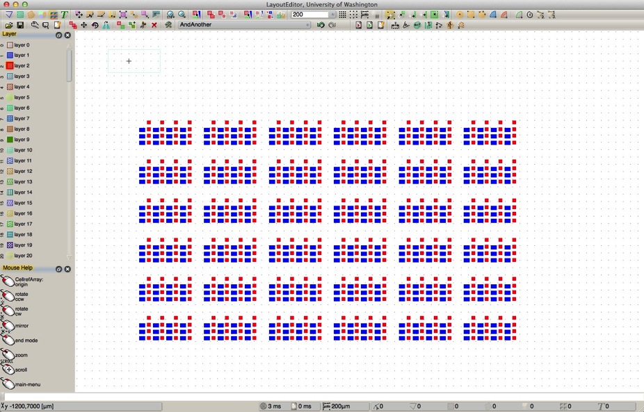
A key point to remember about this hierarchy: in the example array in this last figure, my entire CAD database consists of just 6 cells, one polygon with 64 vertices, one box, and 4 array instances, consuming just 20,984 bytes for the entire library file.
However, when I “flatten” the data so that there is no longer any hierarchy, there are now 362,880 objects consuming a file size of 189,133,242 bytes!!
All this extra data for no additional information! The design results in exactly the same shapes! Hierarchy is good.
That said, there are valid reasons why you might have to flatten parts of your data, at least to some extent. For example, there may be geometric properties such as feature size that you intentionally need to vary in different areas of your design. Just recognize that it will make your file sizes much larger, and possibly increase your ebeam expose or mask-making time.
If possible, before you being your design, it's helpful to think a bit about what variations you might want to have in your design, and what "building blocks" might be common in your design. The more re-use you can get out of the same design cell, the more efficient your design creation will be, and more importantly, more efficient updates and changes to your design will be.
Top-Down vs Bottom-Up
From the overall design viewpoint, there are two distinct directions you can come at a new design. You could start at the top - by designing your entire wafer or chip layout, and then populating your designs or devices within that area. Or, you could start by designing the most simple, fundamental unit of your design, the building up arrays and structures and variations on those fundamental units, and build up until you have your entire chip or wafer design completed. Both strategies are perfectly valid, and for most academic projects, a combination of both techniques are used. It's usually not possible to start by listing every variation you're going to want, or plan your entire wafer before you start. There's nothing wrong with working from both the top and bottom at the same time. Try to keep your data organized, by using description cell and layer names, so that as your design grows in complexity, you'll still be able to navigate through the various parts, and again, try to utilize structured hierarchy whenever possible; it's the most efficient sort of design you can do.
The next page has another example, of a device that looks more like a transistor.
Or, if you’re feeling confident and want to delve into more details, jump to this page, which has lots more picky details and design advice.