Layout Example # 1 Using KLayout: Gratings, 1-D and 2-D
OK, let’s step through the process of creating a simple design in KLayout. My screenshots are from my Mac, but it behaves pretty much the same way on Windows and Linux. If you haven’t downloaded KLayout yet, go download it here and install it on your computer.
First, KLayout has two very distinct operating modes: VIEWER and EDITOR. If you start KLayout and you only see Select, Move and Ruler in the toolbar, but no other options, then you are in Viewer mode, and you can’t edit anything. Select Preferences (Setup for you windows folks), then under Application:Editing Mode, check the box “Use editing mode by default”, quit and restart KLayout and you should be in edit mode with 9 different options in the toolbar. (Update: KLayout now nicely displays a dialog telling you this same information when you start up in viewer mode.)
First, you need to create a “Layout”. A “layout” contains all of the objects and layers in your design, and in general, you’ll use one layout for each distinct project. (You can think of a “layout” as a document in Microsoft Word -- inside that document, you’ll have many objects, words, paragraphs, titles, etc, but everything is in a single container, in this case, a “layout”.)
Select File : New Layout, and get this dialog:
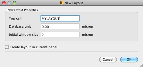
You’ll have to choose a name for the “Top Cell” -- this is the top of your hierarchy in your design. When you send your mask data to a mask shop, or to LayoutBEAMER for the JEOL ebeam, you’ll need to tell that software what cell in your library is your “Top Cell”. (Really, though, the cell name you enter here is just the first cell in your library -- any cell you create can become the “top cell” as you build hierarchy.) For your database unit, if you are planning an ebeam exposure, I highly recommend you use “0.001”, ie. 1 nm. The number here will be the smallest possible increment in your cad design. The Initial Window Size doesn’t really matter; it’s just the size of the displayed window -- you can always zoom in or out as you wish from this size. Once you click “OK”, you’ll notice that a new cell name appears under the Cells list on the left side of the window. (Also note that KLayout is very configurable, so it is possible to rearrange or hide most objects in the program, so when I say “The Cell List on the Left Side of the Window”, I’m referring to the default configuration. If you start moving objects around, you’ll have to keep track of their location yourself :)
Once you’ve got a layout open, you need to do a few more steps before you can create any objects. You’ll need to create at least one layer to put objects on. Select menu item Edit : Layer : New Layer...
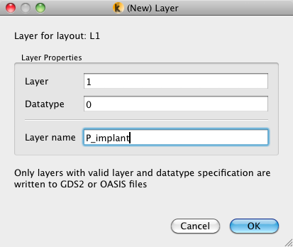
Here, choose a Layer Number, from 0 to 63, skip the Datatype item for now (further discussion of Layers and Datatypes on this page), and optionally enter a Layer Name, which is perhaps more meaningful to you than “17”. Again, the GDS-II standard only uses numbers, but KLayout (and many other CAD programs) let you use more meaningful text names. But when you output the GDS-II file to a mask shop or to ebeam, you’ll still need to specify the actual layer number, because layer names are not stored and transferred in GDS-II files. After you click “OK”, you’ll notice your new layer will appear in the “Layers” list on the right side of the KLayout window.
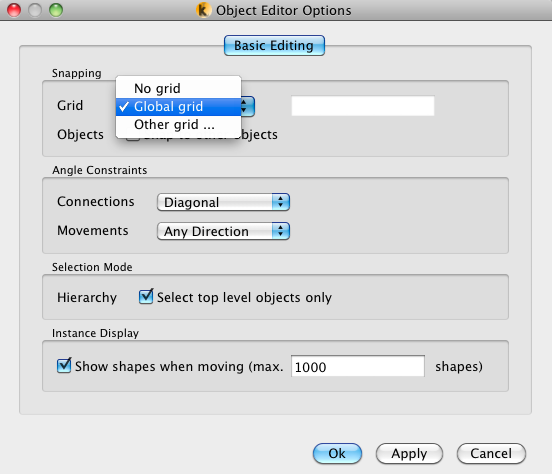
One more detail: creating objects with specific sizes is often easier if you use a design grid, where points you enter are “snapped” to the nearest grid point. It’s a bit like drawing with a pencil on graph paper -- the grid helps you keep everything aligned and at the desired size. Of course, grid settings are very configurable, so you first have to set up the grid you want to use (and it’s common in many layout tasks to use different grid settings for different parts of a layout. First, under the View Menu, make sure “Show Grid” is checked yes. Now, you can select the grid you want to use in several different ways. (1) The longer, but more flexible way is through the Object Editor Options dialog, via [ Edit : Editor Options...]
The first option let’s you select whether to use “No Grid” (seldom recommended), a “Global Grid”, or specify any other grid you might want to use. You can always specify any grid you want with “Other Grid...”.
But for grids you use commonly, you might want to setup a shortcut menu, using Preferences : Application : Default Grid, and enter a list of the grids you use most. You can then quickly select any of these grids with the View : Grid : submenu, shown below. Here’s I’m using the Grid submenu to quickly set my grid to 1 um., but I can achieve the same result the “long” way through Object Editor Options [ Edit : Editor Options...] under the subheading “Snapping”, select Grid “Other” and enter 1 um in the box.)
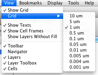
Anyway, get the grid set to 1 um by either the shortcut menu, or the longer “Grid Other” option.
And now, let’s try creating some objects. Let’s start simple and make a 1-Dimensional Grating, which will look like a bunch of parallel lines.
I’m using two layers, I’m calling them “Layer 1” and “Layer 2”, [ Edit : Layer : New Layer...] and I’ve set them to display in Blue and Red [ Layer Toolbox ], but of course, you can use whatever layers or colors you like.
Create a new cell called one_line_2um. [ Edit : Cell : New Cell... ]
Select Layer 1 in the layers list, and select “Box” from the toolbar, and click at (0,0) and then (1,100). This makes a box 1 um wide and 100 um long. Notice that as you move the cursor around the screen, the position “snaps” to the nearest grid point. Also notice that the actual cursor position is always shown in the lower right corner. In creating these two corners of your box, you will like need to scroll or zoom in or out. There are many options for changing your view, mostly under the “Display” menu.
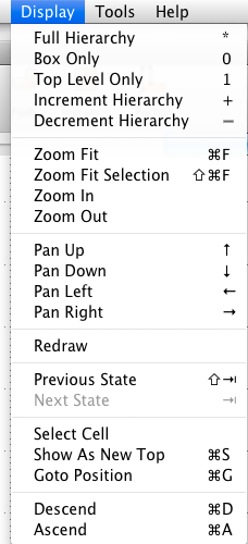
Of course, there are keyboard and mouse shortcuts for many of these options. You can pan your view using the arrow keys, and you can zoom using the mouse wheel. You can also pan by holding shift, then right-click drag in the window to slide the window with the mouse, a bit like in Google Maps. Once you create some objects, take some time to get used to changing your view.
Alternatively, here’s another way you might find easier to get a box of an exact dimension: start by just drawing a box of arbitrary dimensions by clicking any two (different) points. Then choose “Select” in the toolbar (you can use the keyboard shortcut “Esc” to jump back to “Select” at any time). Now double-click the box you just created, and you should see the “Object Properties” box open up. Here, you can set the coordinates of the box exactly to be (0,0), (1,100). Note: In KLayout dialogs, you often must click “Apply” before you close the dialog. I think this is a Unix-y behavior, but it lets you keep the dialog box open while you keep editing. You’ll get used to this if you aren’t already a Unix user.
So cell one_line_2um might now look like this:
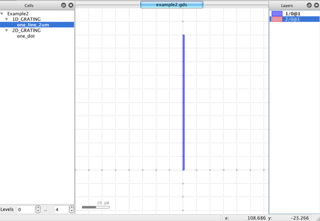
Now make another new cell, called “1D_GRATING”. [ Edit : Cell : New Cell... ] Notice that when you create a new cell, you automatically start editing that cell instead of the cell you were editing before. Also, don’t worry if your cell doesn’t look exactly like this -- this is just a tutorial for you to get familiar with editing, we aren’t making a real device here. )
In this new, empty “1D_GRATING” cell, let’s create an array of those lines by choosing “Instance” from the Toolbar. In the “Object Editor Options” pop-up, click the “...” button to the right of the Cell window and choose the “one_line_2um” cell you created just above. Leave “Scale factor” at 1, Angle at 0, and Mirror Unchecked (for now, feel free to try these out later, though -- they can be very useful!). Click the “Array Instance” box ON. Enter Rows = 1, Columns = 40, Row vector (0,0) and Column Vector (2, 0). Now click the “Apply” button. Notice that now as you move the mouse over the drawing area, you’ll see the outline of a your grating - 40 parallel lines (you may need to zoom out (mouse wheel) to see the outline.) Click on a location in your layout to place your array in your “1D_GRATING” cell. Note that this, like the other shape commands, are iterative, so if you keep clicking, you’ll keep adding more copies of the array! If you want to stop adding arrays, click on “Select” in the toolbar (or press the “Esc” key.)
And your 1-D grating might look like this:
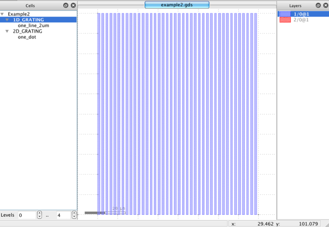
Not too bad -- 40 lines with just a few mouse clicks. But remember, from the discussion on the previous page, this isn’t exactly 40 lines -- it’s really one line, repeated in one array 40 times. So it’s really just two objects: a box (in one cell), and an array (in another cell).
Once in “Select” mode, you can select the array you just created by clicking on that array (or any other object in your drawing). As with many programs, “selected” objects show as a black outline. You can select multiple objects with control-select, and you can select all of the objects in a given area but dragging a window with the left mouse button held down. Once you have one or more objects selected, you can delete, or move, or change properties. For a single object, you can also just double-click on an object to open the “Object Properties” window.
Take some time to pPractice moving around a bit, zooming in and out, panning, etc. Create some new objects, add more instances of your array, maybe try out scaling or rotation. Edit some of the arrays you’ve placed. This is your drawing, do what you like!
When you’re ready to move on, create another new cell, let’s call it “one_dot”. Select “Layer 2” and create a square box (or polygon, as you wish) from (0,0) to (1,1). That is, a square that is 1 micron on each side. That might look like this:
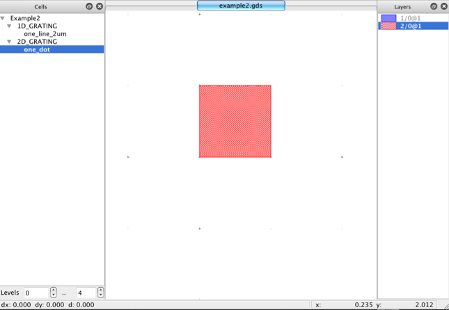
Next, create another new cell, “2D_GRATING”. In this cell, place an Instance of “one_dot” that is 200 x 200 placements of the “one_dot” cell, and spaced say 3 um by 4 um.
And here’s what a 2-D grating might look like:
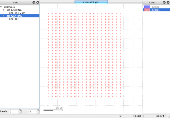
Now you have a 2-dimensional array of 40,000 squares. But let’s say you determine that squares just aren’t cool anymore, and you’d rather have circles. Do you have to change 40,000 squares? No, of course not, because you created your array using hierarchy.
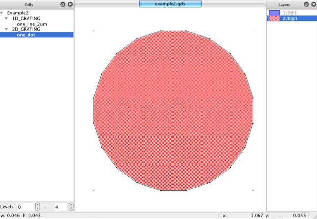
Go back to editing your unit cell, by selecting “one_dot” in the “Cells” menu on the left side, and choosing “Show As New Top”, either from the right-click contextual menu, or from the “Display” menu. Notice that your display now changes to showing just your simple “one_dot”. Click once on the border of your square to select it, (it becomes outlined in black when selected), then choose: Edit : Selection: Round Corners... )You might notice there are lots of enticing options under the Edit : Selection. Come back and explore those in the future -- lots of useful stuff here.) In the dialog box that opens, set the “Outer corner radius” to 0.5 um, and set the “Number of Points” to 20. When you click “OK”, Boom! your once dull square is now a 20-sided polygon, which is a GDS-II approximation of a circle. And might look like this:
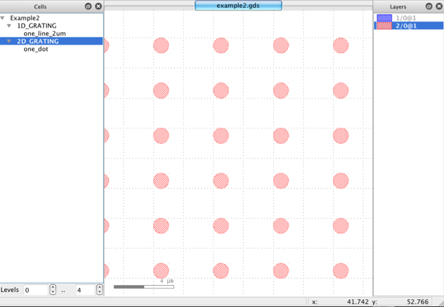
Now, right-click on “2D_GRATING” in the Cells list on the left side, and choose “Show as New Top”, and now you see the entire array of dots now consists of circles instead of squares.
And now your 2-D grating might look like this:
Are you getting the hang of using KLayout to make a design?
Try making another New Cell and placing some instances of your 1D_GRATING and 2D_GRATING cells in this higher-level cell. Yes, you can create cells containing cells containing cells containing cells and so forth, up to 32 levels deep (some programs may allow more; some less.).
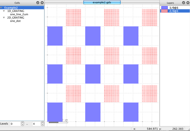
If I then create an array of this cell, that might look like this.... And so on.
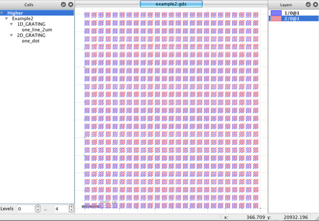
A key point to remember about this hierarchy: in the example array in this last figure, my entire CAD database consists of just 6 cells, one polygon with 20 vertices, one rectangle, and 4 array instances, consuming just 1098 bytes for the entire library file.
However, when I “flatten” the data so that there is no longer any hierarchy, there are now 3,600,000 objects consuming a file size of 923,234,060 bytes!! All this extra data for no additional information. Hierarchy is good. (That said, there are valid reasons why you might have to, at least to some extent, flatten parts of your data. Just recognize that it will make your file sizes much larger, and possibly increase your ebeam expose or mask-making time.)
One very important usage note: For some unknown reason, KLayout does not, by default, map Ctrl-S (or Cmd-S for us Mac people) to “Save”, as most programs do. So it you hit Ctrl-S thinking you are saving your work, well, you aren’t. Be sure to save your work frequently using File:Save. (Of course, you can add a key-mapping to create a shortcut key for Save, under the Preferences or Settings.)
And remember, this is freeware, so you should save your work frequently!!
The next page has another example, of a device that looks more like a transistor.
Or, if you’re feeling confident and want to delve into more details, jump to this page, which has lots more picky details and design advice.
